Introduction
The LVR Circuit device is a simple CPU supervisor device that will keep a CPU in reset until supply voltages have come up to a suitable level for a short amount of time, and will also put a running CPU into reset if the supply voltage drops too low.
Its original design was to prevent the CPU in a Williams 6809-based arcade game or pinball machine from stomping all over the CMOS data when the game is powered down. The 6809 (and some others) are somewhat notorious for executing random writes all over the address space when their +5v line gets too low. Williams accounted for this behavior by implementing a CMOS protection circuit that detects when the power is going down and disables writes to the CMOS memory. That circuit requires that the +12v line go down before the +5v line in order to work correctly.
If you replace the original Williams power supply with a switcher, that circuit may not be able to work correctly because with a switcher, all output voltages collapse at roughly the same time, so the CMOS protection does not have time to kick in before the +5v line drops low enough for the CPU to start acting stupid. This is the cause of occasional CMOS memory issues when using a switcher with that hardware.
A fix for this problem has traditionally been to add a larger capacitor across the +5v line. This should allow the +5v line to stay “up” longer than the +12v line, allowing the CMOS protection circuit to work. This does not always seem to work correctly, and the selection of the size of the capacitor is somewhat of a dark art - too low and it will not work, too high and you may be pulling too hard on your power supply at startup, and might cause it to go into shutdown or pop a fuse.
The original thought of the LVR was simple - just add a CPU supervisor circuit so that it will monitor the power levels and hold the CPU in reset when necessary. This could be accomplished by soldering the supervisor directly to the CPU's pins, but I wanted something a little more elegant, and later thought to extend the functionality to other CPUs as well.
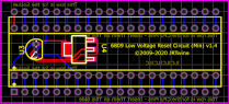
The result is the LVR and the LVR (Custom) circuits (layouts shown until PCBs arrive):


The standard LVR circuit just goes directly in-between the 6809 and the board, and the Custom version can be adapted to just about any 40-Pin (or smaller) CPU that uses a single RESET or /RESET line. The Custom version of the circuit has space for an optional 74LS04, 74HC04 or 4069 inverter which allows it to be used with active-high reset lines.
Since the on-board supervisor holds the CPU in reset until after voltages have stabilized, this also allows the device to be used to implement or replace a Power-On-Reset (POR) circuit. For example, the Custom device can be used on Midway 8080-based hardware to bypass a broken POR circuit.