Table of Contents
Configuring the Custom Circuit
The LVR Custom PVB might look a little busy, but configuring it is pretty simple. First, you need to determine of the target CPU's reset line is active high or active low, this is, RESET or /RESET. If it is active low, you do not need to install the 4096 inverter, but you will if the target CPU's reset signal is active high.
The 4069/74HC04 or 74LS04 Inverter
This inverter is used to take the /RESET signal from the DS1233 circuit and invert it for CPUs that require an active high reset signal, like the 8080 for example. Since the DS1233 can remain functional and provide its /RESET signal down to 1.2v, a CMOS-type inverter is used to maximize the amount of time the corresponding inverted /RESET signal can be provided - the inverted /RESET can be provided down to ~2v, so the circuit will try its hardest to hold the inverted /RESET as long as it can.
If you do not need the inverted /RESET signal to be held to that low a voltage, like if you are using it just to replace the POR circuit on a Midway 8080 board, you can use a standard 74LS04 in place of the 4069. Just be aware that when the voltage drops below normal TTL limits, the 74LS04 will stop working correctly. But since you are only worried about power-up behavior, as opposed to power-down behavior (like you might be with a 6809 CPU), that should not be a problem.
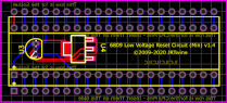
If needed, the inverter is installed at location U1. It can be left unpopulated otherwise.
Configuring the Device
In order to configure the device to a specific CPU, you need to connect the VCC, GND and RESET or /RESET points to the appropriate CPU pins, which are numbered along both sides of the PCB. As mentioned above, if your target CPU uses an active high reset (RESET), you will have to install the inverter and wire up the RESET point to the CPU's corresponding RESET pin. If it uses an active low reset (/RESET), then you would wire up the /RESET point to the CPU's corresponding /RESET pin.
(Note that if you install the inverter, but do not need the inverted /RESET signal, the normal /RESET signal will still function correctly.)
The table below shows how to wire things up for a few different CPU types (please verify any information shown here - mistakes happen!):
| Common CPU Configurations | ||
|---|---|---|
| CPU | Inverter Required | Wiring (Point → Pin#) |
| 8080, 8080A | Yes | VCC → 20, GND → 2, RESET → 12 |
| 6502 | No | VCC → 8, GND → 1, /RESET → 40 |
| Z80 | No | VCC → 11, GND → 29, /RESET → 26 |
| 8086 | Yes | VCC → 40, GND → 20, RESET → 21 |
| 6809 | No | VCC → 7, GND → 1, /RESET → 37 (although the standard LVR circuit was designed for 6809 CPUs) |