This is an old revision of the document!
Table of Contents
Assembling the Device
The LVR and LVR Custom PCBs are very easy to assemble together. All you need is a 40-pin socket for the CPU, a 14-pin socket if you need the inverter to be installed, the DS1233 device and two 20-pin strips for the device connection to the board's CPU socket. The 40-pin socket should be a ladder-type socket, preferably with only one “rung” in the middle of the socket, so that it does not interfere with the placement of the DS1233 device, or the CPU socket pins.
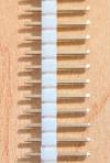
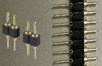
Before we get started, you have to carefully decide on the type of pins you are going to use. If you use standard header-type pins which are commonly used with shorting blocks and look like this:
…those pins are quite a bit larger than standard IC legs and once you insert them into the socket on the board, you will permanently bend the fingers in that socket and that socket will no longer be useful if you remove the device. You should use the thinner strip pins, which are harder to find and are a bit more expensive, which look like this:
Since their pins are smaller, they are less likely to damage the socket. You will also need at least two 40-pin sockets - one for the PCB and one used help align and protect the pins.
The Flip Side
OK - now, identify which side of the board is which. The “parts” side is the side of the board with all of the silkscreen on it, and is where you will be doing most of the part-placing. Conversely, the “solder” side of the board is the side where most of the soldering takes place. On this PCB, you will placing parts and soldering on both sides.
Before you get Started - Sockets vs. Pin Strips
If you choose to do so, you can also use machine pin strip sockets instead of a conventional 40-pin socket as the CPU “socket.” If you do so, I suggest using an old 40-pin chip or a spare socket, insert it into the strip sockets, and use it as a way to align the strip sockets correctly.
Getting Started
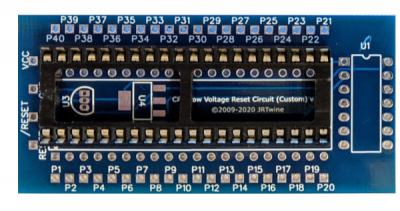
First, you will position the socket that the CPU will plug into. On the parts side of the board, place the 40-pin socket on the board using the pins that are closest to the top of the board (on the Custom board, these are the circular ones closest to the 40-21 silkscreen), and the ones furthest from the bottom of the board. Lightly bend the corner legs a bit so that the socket remains in position when you turn the PCB over to expose the solder side - but do not solder this socket in yet! This will serve as a guide so that you know which holes to solder the pin strips into (the remaining 2 rows - in retrospect, I should have placed markings on the solder side to clearly indicate the holes to use). Here is where the socket should appear in both the 6809 and the Custom versions:
The remaining circular holes are where the CPU pins will go. In order to ensure the strips are aligned correctly and to help protect the pins, insert them into another 40-pin socket, with the longer legs going into the socket, and leaving the shorter legs protruding from the socket. Now align the pins with the two rows of holes from the solder side of the board. Once in place, turn everything over whilst holding the pins in place, remove the placeholder socket off the parts side of the board, and solder the pin strips on the parts side of the board. Leave the socket on these pins to protect them from getting accidentally bent or damaged.
Position the DS1233 Device
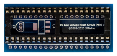
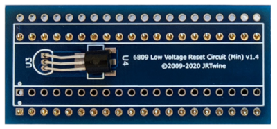
Now, place and solder the DS1233 device. If you use the thru-hole version, leave enough of the leads above the board so that you can bend the device down at a just about a right angle so it fits in the void space that will be left when the socket is soldered in. It should kind looks like this:
Once the device is in the correct position, solder it in place.
Place the CPU Socket
Lastly, place back the 40-pin socket that you first used on the parts side of the board, and solder it in place.
If you have determined you need the inverter (see the Configure page) solder its socket and place it into the socket.
You can now configure the device, as detailed on the Configure page.

