history
Differences
This shows you the differences between two versions of the page.
| Next revision | Previous revision | ||
| history [2020/05/20 09:07] – created adminz | history [2020/05/20 11:43] (current) – jtwine | ||
|---|---|---|---|
| Line 4: | Line 4: | ||
| But when you moved to a switcher, all of the voltages came down at about the same time. This left no time for the CMOS protection circuit to work, and you would get occasional stomping of your CMOS memory. | But when you moved to a switcher, all of the voltages came down at about the same time. This left no time for the CMOS protection circuit to work, and you would get occasional stomping of your CMOS memory. | ||
| + | Back in '09 I figured that since a voltage detection circuit was already possible, I wondered if there were any simplified implementations of them floating around. | ||
| - | Years ago, back when RGVAC was still fresh in people' | + | I never went any further with it because |
| - | Looking further into it, I learned about crowbar circuits which are designed to short out a circuit (generally resulting in a blown fuse, tripped breaker, or power supply shutdown) and discovered that companies made voltage sensing chips that could be used to implement a crowbar circuit. The Motorola (later On Semiconductor) MC3423 was of particular interest to me. | + | I figure a target of $5 for just the PCB? Dunno if I want to be selling assembled units. |
| - | + | ||
| - | Back in '09 while between jobs, I decided to try to implement something. It ended up being a small tangle of wires and parts on perf board, but it worked and did what it was supposed to do - I turned up the voltage and it blew the fuse. I started a new job soon thereafter and never thought about it again. | + | |
| - | + | ||
| - | However, I recently came across a post in one of the arcade repair related groups I frequent which was discussing " | + | |
| - | + | ||
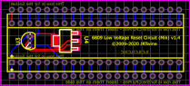
| - | The result is the **JRTwine Crowbar Circuit** device. | + | |
| - | + | ||
| - | I am currently testing out different applications with different people right now. The goal is to sell the device as either a bare PCB board, or as a partial kit containing the following components: | + | |
| - | * MC3423 IC | + | |
| - | * 8-Pin Socket | + | |
| - | * 2N6505 SCR | + | |
| - | * Fuse holder or fuse clips (depending on supply, maybe optional? | + | |
| - | (Customers will have to provide their own resistors and LED.) | + | |
| - | + | ||
| - | I figure a target of around $10 works for the kit, and maybe $3-4 for just the PCB? Dunno if I want to be selling assembled units. | + | |
history.1589983656.txt.gz · Last modified: 2020/05/20 09:07 by adminz