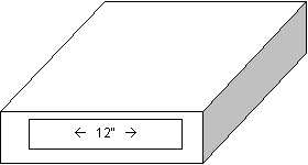
The PortaJAMMA is an idea that I have had for creating a portable JAMMA/AAMA test rig, which could be used for rapid testing of PCBs on-location, such as in a Warehouse, or an Auction area, and can still be functional enough to be used as a rig for a test-bench. The PortaJAMMA is a small, self-contained unit that gives the user the ability to verify the basic functionality of a JAMMA PCB.
One of the basic design philosophies was to slightly sacrifice “playability” for size. As such, the switches (controls) used in the PortaJAMMA are not normal full-sized joysticks and buttons. Instead, two 12-key keypads are used. This gives enough switches to completely exercise all normal inputs available on a standard JAMMA/AAMA interface.
The case for the PortaJAMMA contains more than enough room for the encased power input, fuse block, filter, power-supply, monitor, speaker(s), keypads, switches, and required internal wiring. The top of the case also has a PCB holder mounted onto to it, which can be used to hold multiple-board PCBs that may have lost their standoffs. An initial concept for the case is shown here:

The concept case is 12" wide, ~16” deep and ~6” high.
The monitor is a 5” Samtron CGA monitor,
which is the monitor described in a document written by “Tim” (Powerjaw). [Search for “samtron arcade
monitor powerjaw” to find this document.] The monitor will be
modified and connected using the information contained in that
document. The monitor is [still] available from http://www.digisys.net/timeline/blowout.html.
(Future plans include the addition of a built-in video inverter circuit, which
can be enabled or disabled by a toggle switch.)
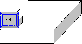
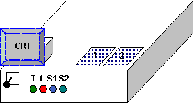
The monitor will be mounted near the front-left
of the case (or recessed diagonally into the case, to help protect the tube and
chassis) as shown here:
Update: I have taken under consideration the use of a lighter, smaller LCD-type display. There are several that I am looking at, more details as things progress.
(Another idea was to use an LCD display with an appropriate signal converter.)
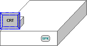
A speaker will be mounted on the inside-front of the case. There is enough room to support two speakers, and there is the possibility of mounting an additional speaker with the addition of a switch to make/break the connection to JAMMA/AAMA pins 11/M. (Future plans include a built-in LM386 or similar amp. which can be enabled or disabled through a toggle switch.) A concept is shown below:
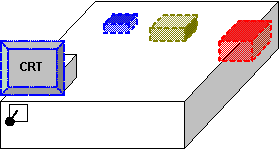
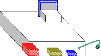
The power supply will be either a low-profile PC power supply, or a switcher (or two) with a fan. The Power Supply needs to be able to supply both the PCB under test and the Monitor at the same time. Associated with the Power Supply(•) will be a filter(•), line cord with strain relief(•) , fuse block(•) [for the input and outputs], and a power switch mounted on the front of the case. A concept of the front and back follow:
Almost all of the game’s inputs will be
connected to the keypads. The “Aux” inputs shown on the keypad will
be for JAMMA+ type boards, or JAMMA boards that make use of the additional,
normally unused, pins on the JAMMA connector (the AAMA connector standard uses
them, for example). The keypad layout will be as follows (for each
player’s associated inputs):
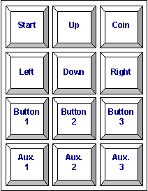
(Note that the PortaJAMMA design only includes keypads for 2 sets of player inputs.)
The Keypads will be mounted near the
front-right of the case, so that they are basically alongside the
Monitor. Also, mounted to the front of the case, “below” the monitor,
will be on-off (not momentary) pushbuttons
for the JAMMA/AAMA switches Test,
Tilt, Service, and
Service 2 inputs. (Future plans include
additional toggle switches to enable or disable a built in 74LS04 -based video inverter and sound
amp.)
The last, but by no means least, part of the PortaJAMMA is the JAMMA/AAMA harness/connector itself. The JAMMA/AAMA harness will protrude from the front of the unit with a strain relief, and will be as long as possible (5-6’). Along with the JAMMA connector there may be additional header-style connectors, for games that have additional player inputs (Street Fighter, for example), which will be wired to the Aux keys on the keypads.
A carrying handle and/or strap can be mounted to the right or left side of the unit. With the monitor and power system located at opposite ends of the unit, the weight difference should be minimal, which would allow the unit to be carried easily.
-=- James R. Twine (jtwine@jrtwine.com)
http://www.jrtwine.com/jtwine/arcade/